Louver Wall Systems: Design, Installation, and Applications
A louver wall serves as both a ventilation component and an architectural feature of the building envelope. By regulating airflow and deflecting rain, debris, and sunlight, it protects what’s behind it. That’s not theory, it’s mechanical protection at work. Air Performance engineers these assemblies for consistent airflow, structural strength, and drainage efficiency across façades, penthouses, and mechanical intakes.
What Is a Louver Wall?
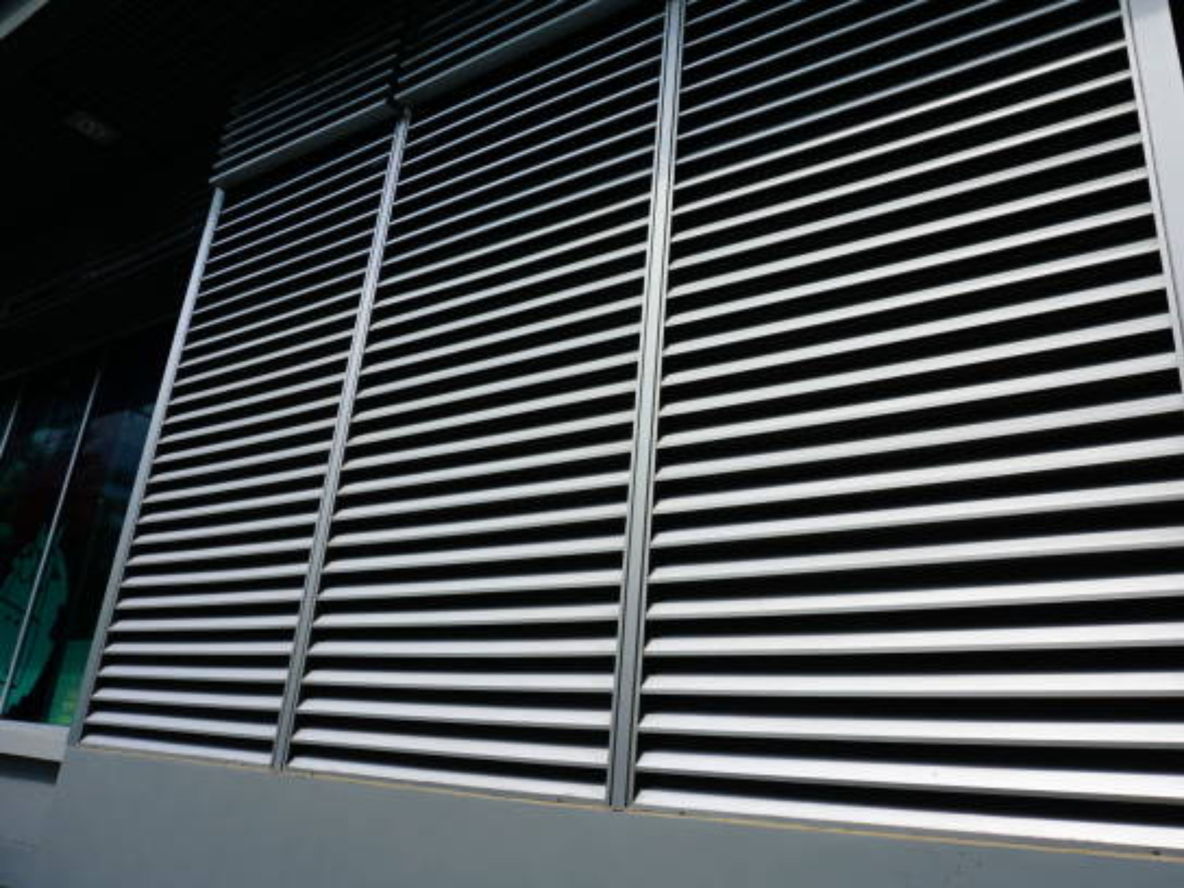
A louver wall system consists of interlocking panels with angled blades held in a rigid frame. The blade geometry directs air while shedding water, and spacing determines free area, airflow capacity, and pressure drop. Unlike small vent openings, these walls can span large mechanical zones or full façades, forming an integrated barrier that reduces rain penetration while maintaining design airflow.
Engineers and architects specify these systems based on airflow rate, face velocity, and exposure. Each blade’s depth, curvature, and spacing control how efficiently air moves and how effectively water drains. That balance defines every system design, requiring close coordination between performance and architectural intent.
Louver Wall Design Considerations
Designing an effective louver wall system involves balancing airflow, drainage, structure, and visual alignment to meet both mechanical and architectural goals.
Blade Orientation and Function
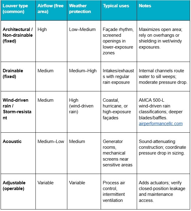
Horizontal layouts dominate because they naturally shed water and align visually with most façades. Vertical units appear when horizontal sightlines must remain clear or directional airflow is required. Operable louvers allow adjustable intake or exhaust, while fixed systems maintain constant geometry and tested performance under AMCA 500-L.
System Configuration and Material Selection
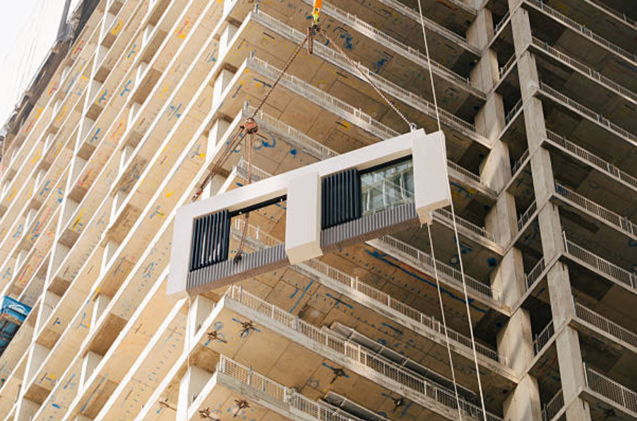
Continuous configurations stretch across long façades with concealed joints, preserving a uniform blade rhythm. Modular panels, sometimes delivered as panel kits, simplify transport and installation. Aluminum remains the preferred material for its strength, corrosion resistance, and low maintenance. Finishes such as anodized or powder coatings extend durability and color consistency.
Aerodynamic and Drainage Performance
The aerodynamic performance of each assembly depends on free area, pressure drop, and water penetration. Drainable blades route water through internal channels toward sill weeps; non-drainable profiles maximize airflow where exposure is limited. Free-area values typically range between 35% and 60%, depending on blade geometry and spacing.
Installation and Detailing
Proper installation ensures that each louver wall system maintains its rated airflow, weather resistance, and structural stability through precise alignment, sealing, and support.
Panel Alignment and Attachment
Installation begins with a properly engineered subframe that carries wind and dead loads back to structure. Installers align and level each panel before fastening through pre-punched holes or hidden clips, depending on design. On long runs, slip joints or slotted fasteners accommodate thermal expansion. Small misalignments can interrupt blade continuity, so tolerance control is essential.
Sealing and Weatherproofing
Sealing and flashing define the weather performance of any wall-mounted assembly. Perimeter sealants close gaps between the frame and wall construction, while head and sill flashings direct water outward. Drainable systems rely on sloped sills and internal channels that move water to designated weep points. Each detail must coordinate with adjacent air barriers, insulation, and façade materials to keep the envelope continuous.
Digital Modeling and Coordination
Digital modeling supports this coordination. In BIM environments, a Revit louver wall family can be created to visualize assemblies, embed free-area and pressure-drop data, and detect clashes before fabrication. Using this approach during design coordination helps ensure accurate alignment across architectural, mechanical, and structural disciplines.
Anchorage and Structural Back-Up
Large spans and multi-bay runs require an engineered support strategy that transfers design wind loads back to structure without inducing blade bow or mullion vibration. Subframes and clip details should be selected to carry point loads at anchors, with splice continuity where panels interface. On wide bays, use multi-point framing or internal retention brackets to prevent screen sag and flutter; verify anchor layout and fastener capacity against project wind pressures.
Field Testing and Commissioning
After installation, contractors inspect blades, drain paths, and perimeter seals. Where required, airflow and water-penetration tests confirm compliance with design intent. In critical mechanical intakes or generator housings, these verifications prove that the system performs under load, steady airflow, no leaks, no surprises. That’s where precision matters.
Performance benchmark: Select models are tested and rated per AMCA 500-L/511, with published water-penetration maximums as low as 0.01 oz/ft² on specific product sheets. Verify the applicable certified ratings during submittal review.
Applications of Louver Wall Systems
Louver wall assemblies appear in diverse building types where airflow, screening, and visual consistency must coexist within the exterior envelope.
Mechanical Enclosures and Equipment Screens
In mechanical enclosures, louvers ventilate while concealing equipment. A louver screen wall can hide air handlers or exhaust stacks from view without restricting circulation. Because these systems are lightweight and modular, crews can mount them directly to structural steel or existing parapets without overloading the frame.
Parking Garage Ventilation
Parking garages rely on such assemblies for natural ventilation that meets code-required air-exchange rates and mitigates wind pressure. In these projects, louvers also shape the façade aesthetic by balancing open area and structural rhythm.
Specialized Configurations
A fire-rated wall louver may incorporate damper assemblies that close under heat to maintain fire separation. Storm-resistant profiles use deeper blades and internal baffles tested for wind-driven rain. Acoustic versions reduce equipment noise while maintaining ventilation in generator or plant rooms. Each variation extends the concept to specific safety or environmental requirements.
Coordination and Maintenance
Design success depends on collaboration. Mechanical engineers calculate required free area and face velocity. Architects align module spacing with façade grids. Structural designers confirm wind-load capacity. Shop drawings document anchorage, flashing, and joints to prevent infiltration. When executed correctly, the installation maintains both appearance and mechanical function.
Maintenance is straightforward. Periodic inspection of drain paths, sealants, and coatings preserves longevity. Aluminum’s corrosion resistance minimizes upkeep; most systems need only occasional washing. A maintained installation can perform for decades without measurable loss of airflow or weather protection.
Air Performance Expertise
Air Performance engineers precision-built architectural louvers, curtain-wall louvers, and louvered equipment screens that integrate into mechanical and façade systems. Each assembly is engineered for airflow accuracy, drainage reliability, and long-term durability—performance verified through decades of field application.
Engineered Louver Wall Systems for Demanding Installations
Air Performance designs and manufactures aluminum assemblies that combine proven airflow management with precise structural alignment and tested drainage geometry. Each unit is built for performance in real-world applications, from mechanical intakes to façade screening, where airflow, weather protection, and appearance must work as one. Contact us today for more information.